The Buzz on Wedge Barriers
An Unbiased View of Wedge Barriers
Table of ContentsLittle Known Questions About Wedge Barriers.All About Wedge Barriers
18 may be done quicker, easily, and expense successfully. FIG. In specific embodiments, the support 30 might be a steel structure including plates, light beams(e. g., I-beams ), and/or various other structures that are protected within the foundation 14, which may be concrete. At the surface area 12, a top side 28 of the anchor 30 may go to least partially exposed
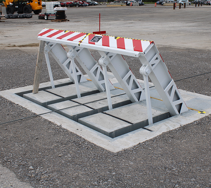
, thereby allowing the attachment of the obstacle 10 to the support 30. g., threaded holes)in one or more beams or plates of the support 30 may be exposed to the surface 12. In this way, screws 32 or various other mechanical fasteners might be used to safeguard the obstacle 10 to the support 30. As the barrier 10 is installed to the surface 12 of the structure 14, collection of particles and other material underneath the barrier may be reduced, and elements of the bather 10 might not be revealed to below quality atmospheres. As indicated by referral numeral 52, the training system 50 consists of components got rid of under the wedge plate 16. For instance, the components 52 beneath the wedge plate 16 might consist of an electromechanical actuator, a webcam, several camera surfaces, and so forth. Furthermore, the lifting mechanism 50 includes a springtime assembly 54
The spring pole 58 is coupled to a web cam(e. g., webcam 80 shown in FIG. 4) of the training device 50. The springs 60 disposed regarding the springtime rod 58 are kept in compression by spring supports 62, consisting of a taken care of springtime assistance 64. That is, the set springtime assistance 64 is dealt with about the structure 14 and the rest of the bather 10.
The 9-Minute Rule for Wedge Barriers
g., springtime support 65 )might be dealt with to completion of the spring rod 58 to enable compression of the springtimes 60. As the springs 60 are pressed in between the springtime supports 62, the spring assembly 54 creates a pressure acting upon the web cam coupled to the springtime rod 58 in a direction 66. The remaining pressure used to
the cam webcam deploy release wedge plate 16 may be provided given an electromechanical actuator 84 or other actuator. Because of this, the spring assembly 54 and the actuator 84(e. g., electromechanical actuator)might run with each other to convert the web cam and lift the wedge plate 16.
As pointed out above, the springtime setting up 54 puts in a continuous pressure on the cam, while the electromechanical actuator may be regulated to exert a variable force on the camera, thereby see here enabling the lifting and reducing( i. e., deploying and retracting )of the wedge plate 16. In specific personifications, the consistent pressure applied by the springtime setting up 54 may be flexible. g., electromechanical actuator) is disabled. As will certainly be valued, the springtime assembly 54 may be covered and protected from particles or various other aspects by a cover plate(e. g., cover plate 68 received FIG. 4) that might be significantly flush with the raised surface 38 of the structure 14. As pointed out above, in the released placement, the wedge plate 16 offers to block gain access to or traveling beyond the obstacle 10. The barrier 10(e. g., the wedge plate 16 )might block pedestrians or automobiles from accessing a property or pathway. As discussed above, the obstacle 10 is connected to the anchor 30 secured within the structure 14,

front brackets 71. Therefore, the link settings up 72 may pivot and rotate to make it possible for the collapse and expansion of the linkage settings up 72 throughout retraction and implementation of the bather 10. The affiliation settings up 72 cause motion of the wedge plate 16 to be restricted. As an example, if an automobile is traveling in the direction of the deployed wedge plate 16(e. As an example, in one scenario, the security legs 86 may be extended throughoutmaintenance of the barrier 10. When the safety legs 86 are released, the safety and security legs 86 sustain the weight of the wedge plate 16 versus the surface 12. Therefore, the lifting device 50 may be shut down, serviced, gotten rid of, replaced, and so forth. FIG. 5 is partial perspective sight of a personification next of the surface-mounted wedge-style obstacle 10, highlighting the camera 80 and the web cam surfaces 82 of the training device 50. Specifically, 2 camera surfaces 82, which are described as reduced web cam surfaces 83, are positioned listed below the web cam 80. The reduced cam surfaces 83 might be fixed to the surface 12 (e. As an example, the lower camera surfaces 83 and the placing plate 85 might develop a solitary item that is secured to the support 30 by screws or other mechanical fasteners. Furthermore, 2 camera surface areas 82, which are referred to as upper cam surfaces 87, are placed above the cam 80 and coupled to (e. In other personifications, interfering layers or plates may be placed between the surface area 12 and the reduced webcam surface areas 83 and/or the wedge plate 16 and the top camera surfaces 87 As stated over, the web cam
80 translates along the cam surface areas 82 when the wedge plate 16 is raised from the withdrawed position to the released placement. Furthermore, as stated above, the springtime setting up 54 (see FIG. 3 )may give a pressure acting on the webcam 80 in the direction 102 by means of spring rod 58, which might reduce the force the electromechanical actuator view it 84 is needed to put on the web cam 80 in order to actuate and lift the wedge plate 16. 1 )to the deployed setting(see FIG. 4). As shown, the camera 80 includes track wheels 104(e. g., rollers), which call and translate along the cam surface areas 82 during operation.